
micro:bit Reference Design
the micro:bit reference design is 100% binary compatible with the micro:bit but based on an nRF51 module instead of the chip directly on the board - this means you don't need to worry about antenna tuning or radio compliance when you make your own micro:bit derived design.
Reference Design
As well as learning about how the micro:bit is designed from the schematic, we want to enable people to build their own hardware products and projects based on the micro:bit. This means taking all the hardware that you’ve connected to your micro:bit and putting down on one circuit board.
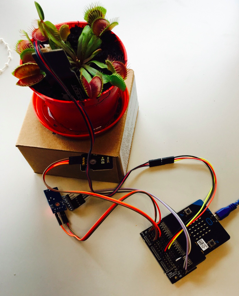
Turn all these cables into a single board!
Because the micro:bit has a Bluetooth radio, building your own boards just like the micro:bit is complicated - you need to tune the antenna, add the right resonance circuit and then certify the board, if you’d like to build more than just a few of them. Therefore, in order to make it easier to build things based on the micro:bit, we’ve made this version of the board that uses a pre-certified nRF51-based module (details in Module Choice below). This way you can take your mind off the gritty RF details and just concentrate on adding your own components to the board.
Furthermore, the micro:bit has a built in programmer and debugger, which is important for a development board, but might not be worth the cost if you’re just building fixed-function product. The programmer on the reference design can be easily extracted and used to program other boards - so you can make one programmer to program all your micro:bit based designs!
Reference Design Features
-
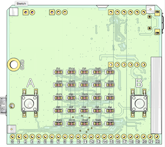
100% binary compatible with the micro:bit, including all the same hardware features: 3xbuttons, 5x5 display, motion sensor)
- Released under the SolderPad License 0.51 (based on Apache-2.0, but tailored towards Open Hardware)
- Based on pre-certified nRF51822 module for ease of use
- Separate programmer and debugger circuits so that you can strip back things that you don’t need
- Standard 2.54mm pitch connector for
- all the micro:bit edge connector pins
- programming the KL26 and the nRF51822
- Modified power supply for more flexible use, standalone regulator
- drive more components without additional power supply
- Use lithium ion polymer batteries as well as AAA (which you shouldn’t do on the micro:bit)
- Design available in Eagle, Altium and KiCad formats
- Coin cell connection and holder option (but beware the dangers of coin cells to children)
Any code that you write for your micro:bit can be run on the reference design without modification.
Modularity
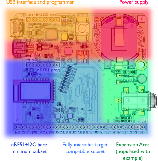
The reference design is laid out in a very modular way, so that someone working with it can easily customise the board to include only the parts they need.
 .
.
For example, if you want to make something really tiny that doesn’t make use of all the expansion or the LEDs, you could make use of the ‘bare minimum subset’ section of the board, and have a separate programmer.
Module Choice
There are multiple vendors of Bluetooth pre-certified modules based on the nRF51822. But because the micro:bit uses every pin on the nRF51822, only modules that exposes all of the GPIO of the chip can be used. We have initially chosen the Raytac MDBT40-256V3, which is available from outlets like Seedstudio, and commonly used on things like Adafruit BLE boards.
This design is fully open source, and we’re happy to accept pull requests for variants that use other modules, or improvements.
For your own projects, using a different module is as simple as wiring the right pins. The hardware page has a detailed pinmap. Likewise, contributions to this pinmap document for other popular modules are welcome.
There is a list of nRF51822 modules maintained by Nordic Semiconductor, from which you could choose any module that has all 31 GPIOs broken out. If your design doesn’t use all of the pins on the edge connector and you are able to recompile your software for your custom design (for example using Mbed) then you could choose a range of other modules.
Software Bringup
Unlike a micro:bit, your device won’t come pre-flashed! Neither of the MCUs will have any software, so you’ll need a debugger, or to ask the people manufacturing your board to flash it for you.
KL26 Software
As described on the interface firmware page, there is a bootloader and a main interface program that needs to be flashed to the KL26.
The hex file/image that contains both of these together can be found here: hex file
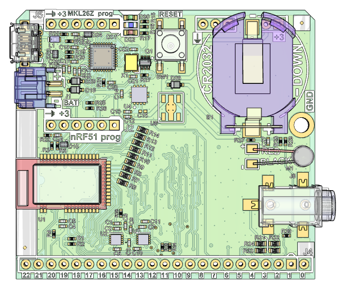
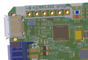
You should flash this onto your KL26 using the header labelled MKL26 prog:
If you don’t have a debugger, the nRF51-DK board can be used as a J-link debugger with the following configuration.
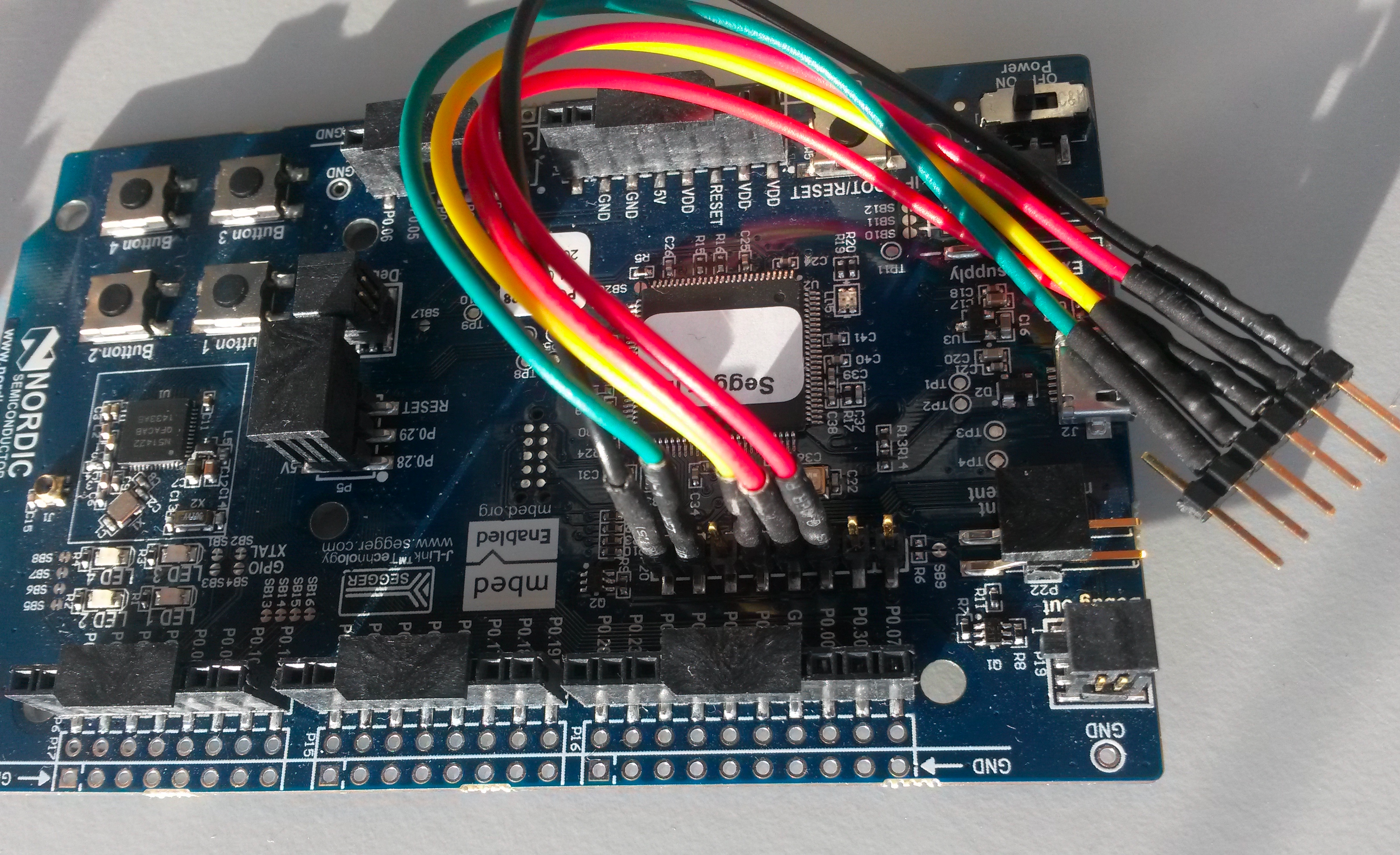
Please see this page for more information.
nRF51 Software
Once you have flashed the KL26 then you can use the USB interface on the reference design itself in order to program any micro:bit hex file onto the device.
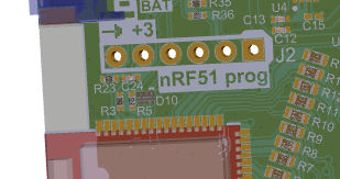
If you have chosen not to include a KL26 circuit then you can use an external programmer and the nRF51prog header:
Design and BOM
The documentation of the reference design is hosted at GitHub where schematics, BOM and layout are all included.
micro:bit reference design GitHub page
The reference design uses the same ICs as the micro:bit itself, so to avoid duplication of documentation, please refer to the micro:bit hardware page for further details.
Design Software
The reference design is provided in formats that can be loaded and used in:
Currently, the design is ‘Altium First’ and we would appreciate any support or expertise around improving the conversion to KiCad and Eagle formats.
If anyone has experience with Eagle import, and needs any Altium / Protel export versions and libraries, they can be supplied, please see this GitHub issue.