
I2C Protocol Specification
Specification for the micro:bit I2C Protocol
micro:bit I2C Protocol Specification
This is version 2.03 of the specification.
- Glossary
- Versioning
- Introduction
- I2C Secondary addresses
- I2C Interface MCU config/comms interface
- I2C Flash Storage Interface
- I2C HID Interface
- Doc Updates
Glossary
| Term | Definition |
|---|---|
| DAPLink | Interface firmware providing USB and programming capabilities |
| I2C | Inter-Integrated Circuit bus |
| I2C main | I2C node in control of the clock and initiating transactions |
| I2C secondary | I2C peripheral that responds to the I2C main |
| Target MCU | The micro:bit microcontroller that runs the user code. The I2C main role in the I2C bus. |
| Interface MCU | The micro:bit microcontroller that provides USB functionality and the I2C secondary role described in this protocol. |
| Storage | Flash available in the Interface MCU for micro:bit data and config storage |
| SWD | Serial Wire Debug |
| UART | Universal asynchronous receiver-transmitter |
Versioning
The version follows a major.minor configuration.
major: Indicates a change or addition to the protocol, this is usually accompanied by a new DAPLink release.minor: Indicates an update, fix, or clarification to the documentation only. No changes required to the protocol implementations.
The I2C protocol version property returns only the major version.
Introduction
The micro:bit contains two microcontrollers (more info in the Tech Site DAPLink page):
- Interface MCU which provides the USB functionality
- Target MCU where the user code runs
In micro:bit V1 there are UART and SWD signals connecting the Interface MCU (KL26) and the Target MCU (nRF51). These are used for the Interface MCU (KL26) to program the Target MCU (nRF51) and to provide serial communication between the Target (nRF51) and the computer.
In micro:bit V1 there is only one I2C bus, connecting the Target MCU to the motions sensors, and the bus is routed to the edge connector (more info in the Tech Site I2C page).
The micro:bit V2 has two I2C buses, an external bus connected from the Target MCU to the edge connector only, and an internal I2C bus connecting:
- The Target MCU (nRF52), as the I2C main device
- The Interface MCU (KL27 in micro:bit V2.0 or nRF52 in micro:bit V2.2), as an I2C secondary device
- The motion sensors, as I2C secondary devices
And all the I2C secondary devices shared a combined interrupt signal to the Target MCU.
This new internal I2C bus allows the Interface MCU to provide additional features to the Target MCU, and to co-operate to set the board into different power modes (more info in the Power Management Spec).
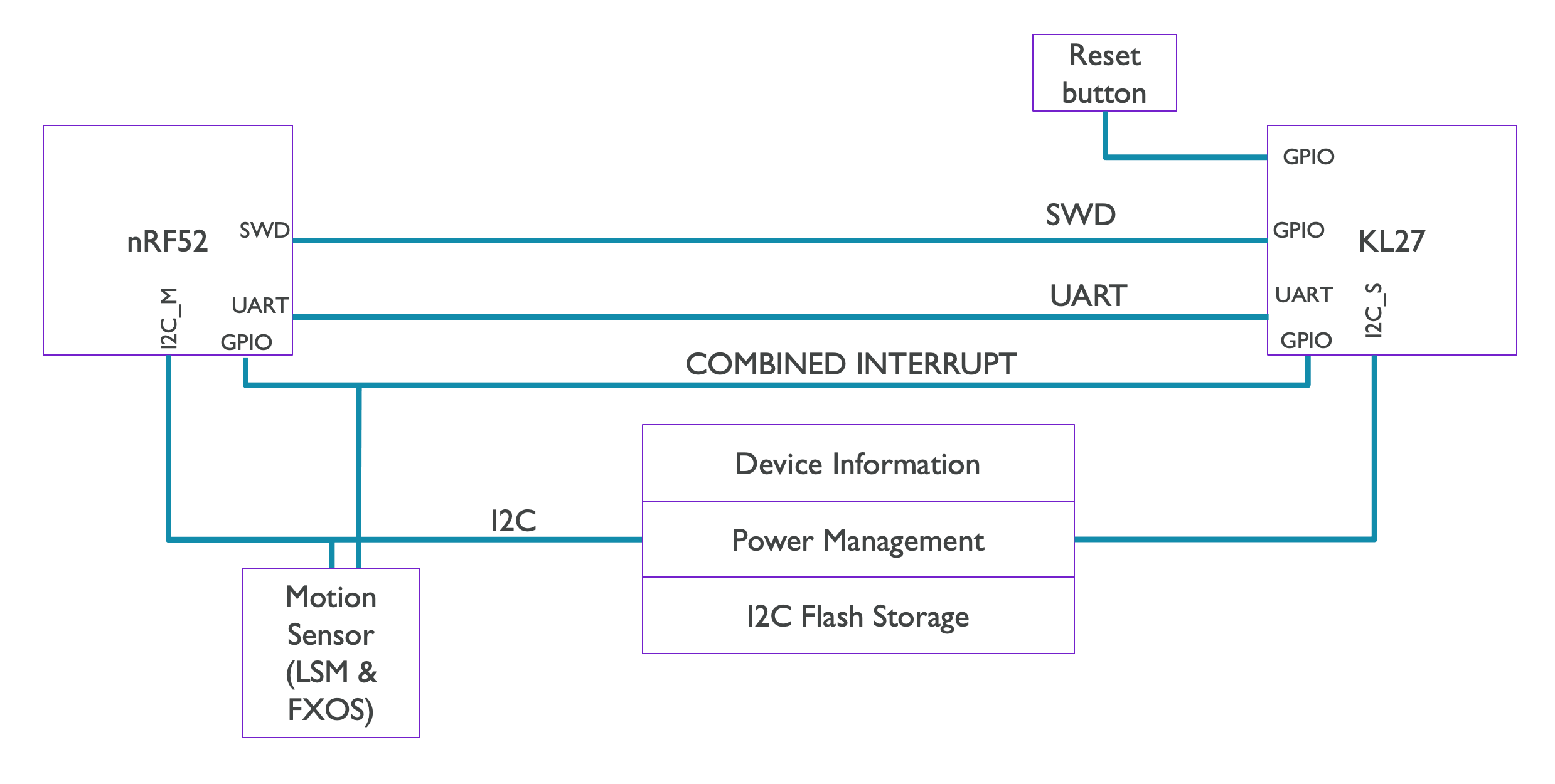
The additional features provided by the Interface MCU via I2C are:
- Device Information
- Board ID, DAPLink version, and more
- Power Management
- As defined in the Power Management Spec
- I2C Flash Storage
- The Interface MCU flash is 256 KBs, where 128KBs are reserved for non-volatile storage accessible to the Target MCU
I2C Secondary addresses
The Interface MCU has reserved three I2C secondary addresses, although it is only using two at the moment, one for the “config/comms” and another for the “I2C Flash Storage”.
The addresses of the motion sensors are also included in this table for reference.
| I2C Secondary | 7-bit address |
|---|---|
| Interface MCU (I2C config/comms interface) | 0x70 |
| Interface MCU reserved (unused) | 0x71 |
| Interface MCU (I2C Flash Storage interface) | 0x72 |
| FXOS8700CQ Combined motion sensor | 0x1F |
| LSM303AGR Accelerometer | 0x19 |
| LSM303AGR Magnetometer | 0x1E |
I2C Interface MCU config/comms interface
Types of commands
| Command | CMD ID | Used by | Description |
|---|---|---|---|
nop_cmd |
0x00 | main only | A command that does nothing, used for waking up the Interface MCU due to a chip errata. |
read_request |
0x10 | main only | Request by the I2C main to read data from the I2C secondary. |
read_response |
0x11 | secondary only | Response from the I2C secondary from a read request |
write_request |
0x12 | main only | Request by the I2C main to write data to the I2C secondary. |
write_response |
0x13 | secondary only | Response from the I2C secondary from a write request (indicates correct receipt of command) |
error_response |
0x20 | secondary only | Response from the I2C secondary indicating an error |
Packet format for each command
nop_cmd
| ----------- |
| CMD ID (1B) |
| ----------- |
read_request
| ----------- | ---------------- |
| CMD ID (1B) | Property ID (1B) |
| ----------- | ---------------- |
read_response
| ----------- | ---------------- | -------------- | --------- |
| CMD ID (1B) | Property ID (1B) | Data size (1B) | Data (NB) |
| ----------- | ---------------- | -------------- | --------- |
write_request
| ----------- | ---------------- | -------------- | --------- |
| CMD ID (1B) | Property ID (1B) | Data size (1B) | Data (NB) |
| ----------- | ---------------- | -------------- | --------- |
write_response
| ----------- | ---------------- |
| CMD ID (1B) | Property ID (1B) |
| ----------- | ---------------- |
error_response
| ----------- | --------------- |
| CMD ID (1B) | Error code (1B) |
| ----------- | --------------- |
Properties
| Property | R/W | Property ID | Size (bytes) | Data |
|---|---|---|---|---|
| DAPLink Board version | R | 0x01 | 2 | e.g. 0x9904 |
| I2C protocol version | R | 0x02 | 2 |
e.g. 0x0001 Value only includes major version |
| DAPLink version | R | 0x03 | 2 | e.g. 0x00FD |
| Power state | R | 0x04 | 1 |
e.g. 0x01 for "USB Only"
typedef enum {
    PWR_SOURCE_NONE = 0,
    PWR_USB_ONLY = 0b01,
    PWR_BATT_ONLY = 0b10,
    PWR_USB_AND_BATT = 0b11  // (*)
} power_source_t;
"Source None" indicates the micro:bit is powered via the edge connector.* On USB power the battery reading (bit 1) might not be correct due to a hardware bug |
| Power consumption | R | 0x05 | 8 |
First 4B for bat_sense voltage Second 4B for vin voltage Units in microvolts |
| USB enumeration state | R | 0x06 | 1 |
e.g. 0x02 for USB Connected
typedef enum main_usb_connect {
    USB_DISCONNECTED = 0,
    USB_CONNECTING,
    USB_CONNECTED,
    USB_CHECK_CONNECTED,
    USB_CONFIGURED,
    USB_DISCONNECTING
} main_usb_connect_t;
|
| Interface Power mode | W | 0x07 | 1 |
e.g. 0x08Power Down = 0x08There is currently only a single option, which is to request the Interface Power Down mode. For more info: Power Management Spec |
| Power LED Sleep state | W | 0x08 | 1 |
e.g. 0x010x00 -> OFF 0x01 to 0xFF -> ON |
| User event | R async | 0x09 | 1 |
e.g. 0x010x01 -> Wakeup from reset button (not used) 0x02 -> Wakeup from WAKE_ON_EDGE 0x03 -> reset button long pressThis is the only `read_response` that originates from the Interface, without a `read_request`. Triggered when the reset button is pressed, or USB has been inserted. |
| Automatic sleep | W | 0x0A | 1 | e.g. 0x010x00 -> OFF 0x01-0xFF -> ON |
Error codes
| Error | Error Code |
|---|---|
| Incomplete command | 0x31 |
| Unknown command | 0x32 |
| Command disallowed | 0x33 |
| Unknown property (for both read and write requests) | 0x34 |
| Wrong size for property (for write requests) | 0x35 |
| Read property disallowed | 0x36 |
| Write property disallowed | 0x37 |
| Write fail | 0x38 |
| Busy | 0x39 |
Examples
- Read DAPLink Board version (Target I2C main)
read_request(cmd id + property) I2C Write:0x100x01- (Interface processes cmd and asserts
COMBINED_SENSOR_INTsignal when response is ready) read_response(cmd id + property + size + data) I2C Read:0x110x010x020x040x99- (Interface releases
COMBINED_SENSOR_INTsignal)
Considerations
read_requestcan only be sent by the Target I2C main- The I2C main (Target) must wait for the
COMBINED_SENSOR_INTsignal to be asserted by the secondary (Interface)
- The I2C main (Target) must wait for the
write_requestcan be sent by both secondary and main.- For the secondary to initiate this, it must assert the interrupt signal first and then the main must poll (i2c read) the device for data.
- I2C transactions must not overlap. Every I2C Write, must be followed by an I2C Read.
- I2C Reads can be triggered by other I2C devices activating the shared
COMBINED_SENSOR_INTinterrupt signal. In case a response is not ready by the secondary (Interface), the busy error code will be returned and the main (Target) should re-attempt to read the response when theCOMBINED_SENSOR_INTsignal is asserted.
- I2C Reads can be triggered by other I2C devices activating the shared
I2C Flash Storage Interface
Interface storage memory layout:
↓ Interface flash address 0x20000                           ↓ Interface flash address 0x40000
↓         ↓ Interface flash address 0x20400                 ↓
┌---------┬-------------------------------------------------┐
| Interf. | storage data                                    |
| config  |[ file.ext -------------------- ][ DAL’s config ]|
└---------┴-------------------------------------------------┘
          ↑ storage address 0x0000          ↑ address set by file size
                ↑ encoding window start address (anywhere inside file.ext range)
                            ↑ encoding window end address (anywhere inside file.ext range)
- config
- Controlled by the Interface MCU
- Target MCU reads/write data fields via I2C commands
- data
- Controlled by Target MCU
- Target MCU reads/write bytes via I2C commands
- Storage address range: 0x00000 to max_size
Protocol
- Word (4 Bytes) align transactions
- All transactions start with:
- 1 byte command ID
- N byte data depending on command
- For Interface responses, the Interface will hold interrupt until success/error messages have been served
Commands
- Read/Write config data (stored in RAM)
- File name (includes extension) (cmd id
0x01)- 11B uppercase characters following 8.3 format (e.g.
"DATA BIN") - default → DATA.BIN
- A remount is needed for the file name change to take effect
- 11B uppercase characters following 8.3 format (e.g.
- File size (from start of data section) (
0x02)- 4B size in bytes (MSB First)
- default → 129024 (126 KBs)
- max size is 126 KBs (128KB - 1KB for flash interface config and 1KB for DAL’s config)
- A remount is needed for the file size change to take effect
- Set encoding window (
0x09)- 4B Encoding window start (MSB First)
- 4B Encoding window end (MSB First)
- default → 0 for both values
- min value is 0, max value is the end of file adress
- If encoding window start is equal to encoding window end, no encoding will be done
- A remount is needed for the encoding window to take effect
- Enable file visible in MSD (
0x03)- 1B visibility
- default → false
- A remount is needed for the file visibility change to take effect
- File name (includes extension) (cmd id
- Write config data to flash (
0x04)- Handles sector erase if RAM config data is different than Flash config data
- Erase all config (
0x05)- Config data will be in its default state
- Get available storage size (
0x06)- 1B size in KB
- Get flash sector size (
0x07)- 2B sector size in bytes (MSB first)
- Re-mount MSD (
0x08)
Flash Operations
Reading/writing config data
- For writing the config data (file name, file size and file visibility), the I2C main has to send the 1B command ID followed by the corresponding config data. If the data size is unexpected, an error will be returned in the I2C response.
- The I2C Response after a successful write operation will contain the corresponding command ID followed by the written config data which can be used as confirmation by the I2C main.
- For reading the config data, the I2C main has to send only the 1B command ID with no further data. The I2C response will then contain the config data.
Write storage data
- 1 byte write command (cmd id
0x0B) - 3 bytes address (MSB First)
- 4 bytes for length (MSB First)
- data to write
- Address and size check
- Size has to be a multiple of 4 bytes
- Address has to be aligned to a 4 byte boundary
- Bound check
- Interface can clock stretch
Read storage data
- 1 bytes read command (
0x0A) - 3 bytes address
- 4 bytes for length
Erase storage data
- 1 bytes erase command (
0x0C) - 3 bytes start address
- 1 unused
- 3 byte end address (inclusive)
- For a single sector erase Start address == End address
- Address checks
- Addresses have to be sector align
- End address >= Start address
- Bound check
- On errors Interface to trigger interrupt and send error code
- On success Interface to trigger interrupt and send success message
- KL to provide some kind of status read command
Interface I2C secondary behaviour
- Before enumeration it checks if it should show the file on the MSD
- It sets the file name from the config
- It sets the file size from the config
- Interface I2C buffer size: 1KB + 4 bytes
- Storage writes should not trigger “hidden” sector erases, the Target MCU is responsible to write and erase
- When writing to the config data first check if the data to be written is different than present, avoid an erase-and-write operation if it’s the same
- USB should have higher priority than any I2C transaction
Examples
Storage Write
- Write 4 bytes “1234” to storage address 0x000010
I2C Write:  [0x72,    0x0B,  0x00,0x00,0x10,  0x00,0x00,0x00,0x04,  0x31,0x32,0x33,0x34]
     I2C Addr ↑  cmd id ↑    address ↑        length ↑              data ↑
I2C Read:   [0x72,    0x0B,  0x00,0x00,0x10,  0x00,0x00,0x00,0x04,  0x31,0x32,0x33,0x34]
     I2C Addr ↑  cmd id ↑    address ↑        length ↑              data ↑
Storage Read
- Read 4 bytes at storage address 0x000010
I2C Write:  [0x72,    0x0A,  0x00,0x00,0x10,  0x00,0x00,0x00,0x04]
     I2C Addr ↑  cmd id ↑    address ↑        length ↑
I2C Read:   [0x72,    0x0A,  0x00,0x00,0x10,  0x00,0x00,0x00,0x04,  0x31,0x32,0x33,0x34]
     I2C Addr ↑  cmd id ↑    address ↑        length ↑              data ↑
Config Update, enable file visibility and remount MSD drive
- Change filename to LOG.TXT
I2C Write: [0x72, 0x01, 0x4c,0x4f,0x47,0x20,0x20,0x20,0x20,0x20,0x54,0x58,0x54] I2C Addr ↑ cmd id ↑ filename "LOG TXT" ↑ I2C Read: [0x72, 0x01, 0x4c,0x4f,0x47,0x20,0x20,0x20,0x20,0x20,0x54,0x58,0x54] I2C Addr ↑ cmd id ↑ filename "LOG TXT" ↑ - Enable file visibility
I2C Write: [0x72, 0x03, 0x01] I2C Addr ↑ cmd id ↑ visibility ↑ I2C Read: [0x72, 0x03, 0x01] I2C Addr ↑ cmd id ↑ visibility ↑ - Remount MSD
I2C Write:  [0x72,    0x08]
     I2C Addr ↑  cmd id ↑
I2C Read:   [0x72,    0x08]
     I2C Addr ↑  cmd id ↑
Set encoding window
- Set encoding window to first 1KB
I2C Write:  [0x72,    0x09,   0x00,0x00,0x00,0x00,    0x00,0x00,0x04,0x00]]
     I2C Addr ↑  cmd id ↑    enc window start ↑        enc window end ↑
I2C Read:   [0x72,    0x09,   0x00,0x00,0x00,0x00,    0x00,0x00,0x04,0x00]]
     I2C Addr ↑  cmd id ↑    enc window start ↑        enc window end ↑
Universal Hex
Interface Storage area should be writeable via Universal Hex.
This is not yet implemented.
I2C HID Interface
All I2C features should be available via HID interface, so that it can be accessed via WebUSB.
This is not yet implemented.
Doc Updates
| Version | Changes |
|---|---|
| 1.00 | Initial release, as implemented in DAPLink 0255 |
| 1.01 | Add note to “Power state” property about the hardware issue detecting battery power when USB power is present. |
| 2.00 | Add busy flag error code |
| Add “Set encoding window” command to the I2C Flash interface PR #9 | |
| 2.01 | Fix documentation bug where commands were marked as bidirectional |
| Removed “success” error code as it is unused | |
| 2.02 | Generalise the “I2C secondary” and “KL27” references as “Interface”, as V2.0 and V2.2 use different MCUs (KL27 and nRF52) |
| 2.03 | Added more descriptions and improve formatting |