
Power Supply
Powering the micro:bit via USB, 3V ring and battery
Overview
Power to the micro:bit may be provided via:
- USB connection via the interface chip (which has an on-board regulator)
- A battery plugged into the JST connector.
- The 3V and GND pins on the Edge Connector
- The two rounded rectangular pads on the rear right of the board
Power from the micro:bit can be provided by the 3V and GND pins to small external circuits.
It’s is important to stay within the design parameters of the board:
-
When powered from USB, the on-board interface chip on V1 (KL26) uses its on-chip regulator to provide power, and this chip is rated at a maximum of 120mA.
-
The on-board current budget will vary depending on the use of the display, the Bluetooth, microphone, speaker and other peripherals. You should allow a worst case budget of 30mA for when all on-board peripherals are in use, leaving 90mA V1 / 270mA V2 for circuits plugged into the edge connector.
-
When powered from a battery, the KL chip is not powered up and the USB Indicator LED will not light up.
-
A low-Vf diode is used to switch between sources. The diode prevents back-powering of any source from any other source and means you can have a USB cable and battery pack connected simultaneously.
Key Voltages
As taken from each of the chip datasheets, it can be seen that different devices have slightly different operating voltage ranges and absolute maximum voltages. Manufacturers state the operating voltage range as well as the absolute maximum tolerable by the device. You should never exceed the operating voltage range of any of the devices.
V1 revision
| Device | min | max | absolutemax |
|---|---|---|---|
| NRF51 | 1.8V | 3.6V | 3.9Vabs |
| KL26 | 1.7V | 3.6V | 3.8Vabs |
| LSM303 | 1.71V | 3.6V | 3.6Vabs |
| MMA8653FC | 1.95V | 3.6V | 3.6Vabs |
| MAG3110 | 1.95V | 3.6V | 3.6Vabs |
This table implies an operating voltage range of the micro:bit device as a whole as being 1.8V min (for 1.5 variants) or 1.95V min (for 1.3* variants dictated by the motion sensor) and 3.6V max (dictated by all devices).
V2.00 revision
| Device | min | max | absolutemax |
|---|---|---|---|
| nRF52 | 1.7V | 3.6V | 3.9Vabs |
| KL27 | 1.71V | 3.6V | 3.8Vabs |
| LSM303 | 1.71V | 3.6V | 3.6Vabs |
This table implies an operating voltage range of the micro:bit device as a whole as being 1.7V min and 3.6V max.
V2.2x revision
| Device | min | max | absolutemax |
|---|---|---|---|
| nRF52 (target) | 1.7V | 3.6V | 3.9Vabs |
| nRF52 (interface) | 1.7V | 3.6V | 3.9Vabs |
| LSM303 | 1.71V | 3.6V | 3.6Vabs |
This table implies an operating voltage range of the micro:bit device as a whole as being 1.7V min and 3.6V max.
Practicalities
USB Powering
When powered from USB, the V1 interface MCU’s on-chip regulator is used to provide 3.3V to the rest of the board. The latest revision V2 has a separate regulator on the board.
The KL26 datasheet V1 section 3.8.2, Table 30. “USB VREG electrical specifications” indicates the maximum current from the regulated supply is 120mA. Some of this current is required to run on-board devices, such as the KL26 itself, the nRF application processor, the motion sensor, and the LED display. When Bluetooth is enabled, the current consumption of the nRF increases slightly. You should budget your current requirements for anything you attach to the micro:bit V1 to not exceed about 90mA to give enough safe headroom for worst case with all on-board peripherals in use.
The V2 has an on-board regulator capable to source 300 mA.
This means that if you require more than 90mA V1 / 190mA V2 from the edge connector, (e.g. driving lots of NeoPixels or a small motor) these should have power supplied to them externally. You can back-power the micro:bit via its 3V pad, but please be sure to use a properly regulated supply and a protection diode, as explained below, so that your micro:bit always has a supply within the operating range of all the on-board peripherals and the supplies are not able to power each other.
It is advised that you do not power the micro:bit from USB battery packs. This is because some makes and models of USB battery packs can generate out of range voltages when they are not suitably loaded that could damage your micro:bit (i.e. when a small current is drawn). Also, some USB battery packs will switch off automatically when the current drawn from them is too low.
Battery Powering
When powered from a battery plugged into the top battery connector, the V1 interface chip is not powered up, and the System LED will not be turned on. If your code does not display anything on the display, this might look like the micro:bit is not working, but it is. On micro:bit V2 the battery power goes through the on-board regulator and powers the interface chip as well. If the micro:bit board is not in a sleep mode, the red LED (left of the USB connector) should be light up.
Because the V1 target chip is powered almost directly (there is only one BAT60 diode between the supply and the target nRF51 power rails), a fully charged LiPoly battery that is specified to reach 4.2V will give greater than the 3.6V maximum that the nRF51 can withstand.
There is further information about the battery connection and use in our knowledgebase.
3V Ring Powering
The micro:bit may be powered from the 3V/GND rings on the edge connector. There are also two rounded rectangular pads on the far right of the back of the PCB that can be used to supply power (e.g. solderable pads for a 2xAAA holder that has wires or pins at one edge).
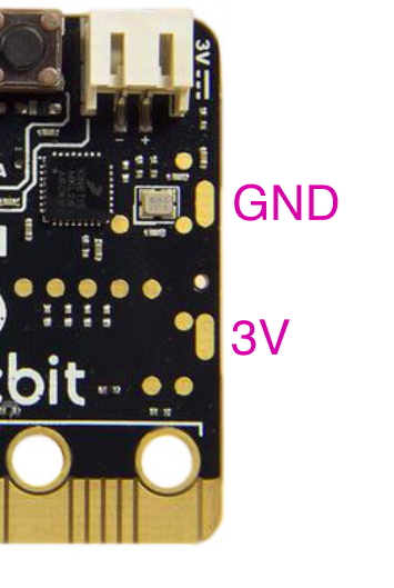
The upper pad is 0V or GND and the lower pad is 3V.
When powering from the 3V ring or the rounded rectangular pads on the PCB, you should take appropriate best practice precautions:
-
Fit an external protection diode (preferably with a low Vf rating) to prevent damage due to the power supply being connected the wrong way round.
-
If powered from a voltage source that could generate a voltage higher than the maximum operating voltage of the micro:bit, fit some form of over voltage protection, or proper regulation.
Power Supply Architecture V1
The schematic shows the architecture of the power supply. Key points to note are that there are two BAT60A diodes, one from the 3.3V supply from the KL26/27 interface chip, and one from the external battery connector. Note that the 3V ring on the edge connector is V_TGT, which is the raw supply provided to all on-board chips, so this is why extra care should be taken when connecting directly to the 3V ring or the 3V rounded rectangular pad.
The BAT60A devices have a low Vf rating, you can read about this in the BAT60A datasheet