1.3x micro:bit revision
Overview
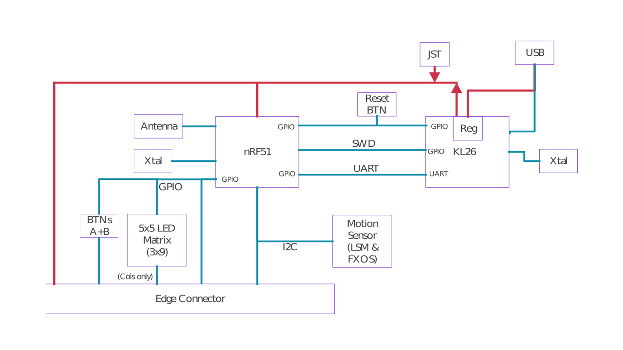
Hardware block diagram
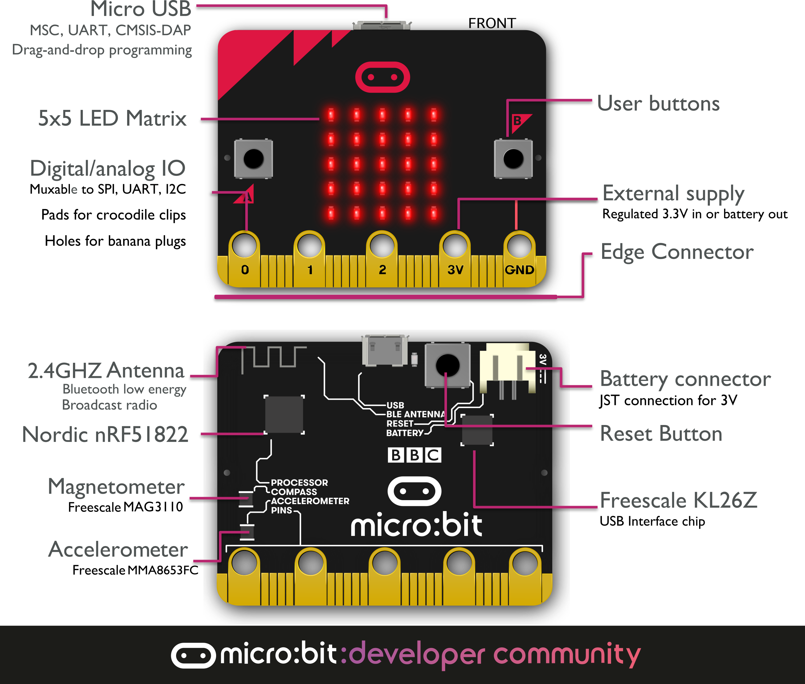
Getting started with the micro:bit hardware
The micro:bit hardware is based on the Arm-Mbed platform. It has an application processor with lots of on-chip peripherals. Some off-chip peripherals are connected to this chip. There is an interface processor connected to the application processor, and it is the interface processors job to manage communications over the USB and to support the drag-and-drop code-flashing process. The interface processor does not connect to any of the micro:bit peripherals.
Two key pieces of information to help understand the internals of the micro:bit are:
-
The schematics, which shows the detailed component data and connectivity of the device.
-
The reference design, which is a complete module design of a compatible micro:bit, and is designed to be a starting point for anyone interested in understanding the micro:bit or designing their own variant.
Hardware description
nRF51 application processor
The nRF51 application processor is where user programs run. A single, complete application including user code, runtime code and bluetooth stack is loaded and run directly from on-chip flash memory. All user accessible GPIO pins are provided by this processor. There is an on-board 2.4GHz radio engine used to provide Bluetooth capabilities via an off-chip aerial.
| item | details |
|---|---|
| Model | Nordic nRF51822-QFAA-R rev 3 |
| Core variant | Arm Cortex-M0 32 bit processor |
| Flash ROM | 256KB |
| RAM | 16KB |
| Speed | 16MHz |
| Debug | SWD, jlink/OB |
| More Info | here |
Bluetooth wireless communication
The on-board 2.4GHz transceiver supports Bluetooth communications via the Nordic S110 SoftDevice, which provides a fully qualified Bluetooth low energy stack. This allows the micro:bit to communicate with a wide range of Bluetooth devices, including smartphones and tablets.
| item | details |
|---|---|
| Stack | Bluetooth 4.1 with Bluetooth low energy |
| Band | 2.4GHz ISM (Industrial, Scientific and Medical) 2.4GHz..2.41GHz |
| Channels | 50 2MHz channels, only 40 used (0 to 39), 3 advertising channels (37,38,39) |
| Sensitivity | -93dBm in Bluetooth low energy mode |
| Tx Power | -20dBM to 4dBm in 4 dB steps |
| Role | GAP Peripheral |
| Congestion avoidance | Adaptive Frequency Hopping |
| Profiles | 1 BBC micro:bit profile |
| More Info | here |
Low level radio communications
The on-board 2.4GHz transciever supports a number of other radio communications standards, on which we build the microbit-radio protocol This protocol provides a very simple small-packet broadcast radio interface between other devices that support it, such as other micro:bit devices. The 'radio' interface that appears in a number of the languages on the micro:bit is built on top of this protocol. Additionally, the micro:bit runtime software adds a 'group code' to each data payload, allowing for simple user managed device addressing and filtering to take place.
| item | details |
|---|---|
| Protocol | Micro:bit Radio |
| Freq band | 2.4GHz |
| Channel rate | 1Mbps or 2Mbps |
| Encryption | None |
| Channels | 101 (0..100) |
| Group codes | 255 |
| Tx power | Eight user configurable settings from 0(-30dbm) to 7 (+4dbm) |
| Payload size | 32 (standard) 255 (if reconfigured) |
| More Info | Micro:bit Radio |
Buttons
The two buttons on the front of the micro:bit, and the 1 button on the back, are tact momentary push to make buttons. The back button is connected to the KL26 interface processor and to the nRF51 processor for system reset purposes. This means that the application will reset regardless of if it is powered from USB or from battery.
Front buttons A and B can be programmed in the user application for any purpose. A and B are debounced by software, which also includes short press, long press, and 'both A+B' press detection. Buttons operate in a typical inverted electrical mode, where a pull-up resistor ensures a logical '1' when the button is released, and a logical '0' when the button is pressed. Both A and B buttons are connected to GPIO pins that are also accessible on the micro:bit edge connector.
| item | details |
|---|---|
| Type | 2 tactile user buttons, 1 tactile system button |
| Debounce | (A & B) software debounced, 54ms period |
| Pullup | (A & B) external 4K7, (System) 10K |
Display
The display is a 5x5 array of LEDs. It is connected to the micro:bit as a 3x9 matrix. Runtime software repeatedly refreshes this matrix at a high speed, such that it is within the user persistence of vision range, and no flicker is detected. This LED matrix is also used to sense ambient light, by repeatedly switching some of the LED drive pins into inputs and sampling the voltage decay time, which is roughly proportional to ambient light levels.
| item | details |
|---|---|
| Type | miniature surface mount red LED |
| Physical structure | 5x5 matrix |
| Electrical structure | 3x9 |
| Intensity control | 10 steps |
| Intensity range | TBC |
| Sensing | ambient light estimation via software algorithm |
| Sensing Range | TBC, 10 levels from off to full on |
| Colour sensitivity | red centric, red is 700nm |
Accelerometer
The accelerometer is a separate chip that provides 3-axis sensing. It also includes some on-board gesture detection (such as fall detection) in hardware, and additional gesture sensing (e.g. logo-up, logo-down, shake) via software algorithms. It is connected to the application processor via the I2C bus.
| item | details |
|---|---|
| Model | Freescale MMA8653FC |
| Features | 3 axes, 2/4/8g ranges |
| Resolution | 10 bits (0..1023) |
| Max output data rate | 800Hz |
| On board gestures | 'freefall' |
| Other gestures | Other gestures are implemented by software algorithms in the runtime. |
Magnetometer
The magnetometer is a separate chip that provides magnetic field strength sensing. A software algorithm in the standard runtime uses the on-board accelerometer to turn these readings into a board orientation independent compass reading. The compass must be calibrated before use, and the calibration process is automatically initiated by the runtime software. This device is connected to the application processor via the I2C bus.
| item | details |
|---|---|
| Model | Freescale MAG3110 |
| Max update rate | 80Hz |
| Full Scale range | 1000uT |
| Sensitivity | 0.10uT |
Temperature sensing
The nRF51 application processor has an on-board core temperature sensor. This is exposed via the standard runtime software, and provides an estimate of ambient temperature.
| item | details |
|---|---|
| Type | on-core nRF51 |
| Sensing range | -25C .. 75C |
| Resolution | 0.25C steps |
| Accuracy | +/-4C (uncalibrated) |
| More Info | here |
General purpose input/output pins
The edge connector brings out many of the GPIO circuits of the application processor. Some of these circuits are shared with other functions of the micro:bit, but many of these extra circuits can be re-allocated to general purpose use if some software features are turned off. Note: the nRF51 datasheet states that GPIO pins may be in std-drive (0.5mA) and high-drive (5mA) mode, with a maximum of 3 pins in high-drive mode at any one time.
| item | details |
|---|---|
| Rings | 3 large IO rings and two large power rings, 4mm plug and crocodile clip compatible |
| GPIO features | 19 assignable GPIO pins |
| 2 are assigned to the on-board I2C interface | |
| 6 are used for display or light sensing feature | |
| 2 are used for on-board button detection | |
| 1 is reserved for an accessibility interface | |
| 19 may be assigned as digital input or digital output | |
| 19 may be assigned for up to 3 simultaneous PWM channels | |
| 19 may be assigned for 1 serial transmit and 1 serial receive channel | |
| 6 may be assigned as analog input pins | |
| 3 may be assigned to an optional SPI communications interface | |
| 3 may be assigned for up to 3 simultaneous touch sensing inputs | |
| ADC resolution | 10 bit (0..1023) |
| Edge connector | Edge connector |
| Pitch | 1.27mm, 80 way double sided. |
| Pads | 5 pads, with 4mm holes |
| More Info | here |
Power supply
Power to the micro:bit may be provided via the USB connection, via the interface chip (which has an on-board regulator), or via a battery plugged into the top connector. It is also possible (with care) to power the micro:bit from the 3V pad at the bottom. The 3V pad at the bottom can be used to supply a small amount of power external circuits.
| item | details |
|---|---|
| Operating range | 1.8V .. 3.6V |
| USB current | 120mA max |
| On-board Peripherals budget | 30mA |
| Battery connector | JST X2B-PH-SM4-TB |
| Battery current | TBC |
| Max current provided via edge connector | 90mA |
| More Info | here |
Interface
The interface chip handles the USB connection, and is used for flashing new code to the micro:bit, sending and receiving serial data back and forth to your main computer.
| item | details |
|---|---|
| Model | Freescale MKL26Z128VFM4 |
| Core variant: | Arm Cortex-M0+ |
| Flash ROM | 128KB |
| RAM | 16KB |
| Speed | 16MHz |
| Debug capabilities | SWD |
| More Info | here |
USB communications
The micro:bit has an on-board USB communications stack, that is built into the firmware of the interface chip. This stack provides the ability to drag and drop files onto the MICROBIT drive in order to load code into the application processor. It also allows serial data to be streamed to and from the micro:bit application processor over USB to an external host computer, and supports the CMSIS-DAP protocol for host debugging of application programs.
| item | details |
|---|---|
| Connector | USB micro, MOLEX_47346-0001 |
| USB version | 1.1 Full Speed device |
| Speed | 12Mbit/sec |
| USB classes supported | Mass Storage Class (MSC) |
| Communications Device Class (CDC) | |
| CMSIS-DAP HID & WinUSB | |
| WebUSB CMSIS-DAP HID | |
| More Info | here |
Debugging
The interface processor can be used with special host tools to debug code that is running on the application processor. It connects to the application processor via 2-pin Serial Wire Debug (SWD). The KL26 interface processor code can also be debugged via its internal SWD software debug interface, for example to load initial bootloader code into this processor at manufacturing time, or to recover a lost bootloader.
| item | details |
|---|---|
| Protocol | Serial Wire Debug (SWD) |
| Options | DAPLink (CMSIS-DAP) |
| JLink/OB (via different firmware) | |
| More Info | here |
Mechanical
We have some nice 2D and 3D CAD drawings and models of the micro:bit including all the important dimensions. These models can be used as a basis for generating really nice marketing and project images of the micro:bit, but also as a basis for accurate manufacture of attachments e.g. via 3D printing.
| item | details |
|---|---|
| Dimensions | 5cm(w) 4cm(h) |
| Weight | 5g |