
DAPLink and the USB interface
The DAPLink software running on the USB interface chip for the micro:bit provides the drag and drop programming and debugging features that make the micro:bit so easy to use.
Target and Interface MCUs
The micro:bit presents itself as a USB disk when it is connected over USB, and can be programmed through this drive without the need to install any drivers. This makes it easier to use as a beginner. Furthermore, no matter what code you run on your micro:bit, or how you manage to crash the device, you can always still put a new program on using the USB connection.This is made possible by having a separate ‘interface chip’ or ‘interface MCU’ on the micro:bit dedicated to USB connections, programming and debugging.
The Interface MCU is a Nordic nRF52833/nRF52820 V2.2x, Freescale KL27 V2.00, or Freescale KL26 V1.
The chip that developers’ code runs on, and that all the peripherals are connected to is called the ‘target MCU’. See the Hardware page and the schematic for more details about how these two devices are connected.
The Target MCU is a Nordic Semiconductor nRF52833 V2 or Nordic Semiconductor nRF51822 V1.
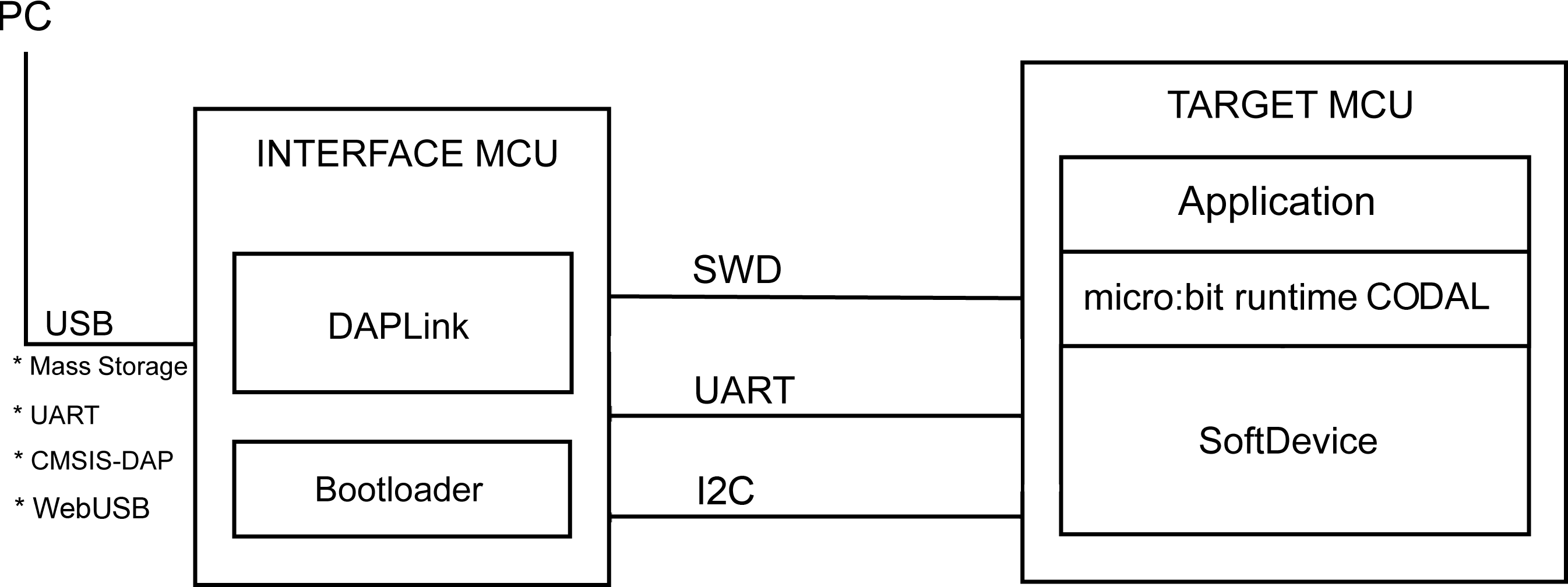
The target and interface MCUs are connected by these interfaces:
-
Serial Wire Debug (SWD) for programming the target MCU.
-
UART for sending messages between the two devices. In practice, the UART from the target MCU is passed through directly to the PC over USB.
-
V2 I2C using a custom protocol.
Reference design
On the reference design the interface circuit is clearly separated from the main micro:bit circuits so that you can do the following things:
-
Build a board without the interface circuitry and use another debugger to program that over SWD.
-
Build a board with just the interface circuitry and use that to flash other hardware that you have built that might be too small to contain its own interface chip.
DAPLink software
This interface chip is running software from Arm Mbed called DAPLink.
This software provides four USB endpoints that have specific purposes:
-
MSC - USB mass storage device for drag-and-drop programming of the target MCU’s flash memory.
-
CDC - serial pass-through from the target MCU to the PC. This is how messages get from the code you write onto the PC.
-
HID - CMSIS-DAP compliant debug channel - this is useful if you want to use advanced debuggers like GDB or Keil to understand what’s happening (or not happening!) on your micro:bit.
-
WebUSB - facilitates communicating with the device via a WebUSB capable browser.
The DAPLink software and interface chip are part of the Arm Mbed HDK
This table shows the device revision and which DAPLink Bootloader and Interface it shipped with:
| Board revision | Bootloader | Interface | Download |
|---|---|---|---|
| 1.3 | 0234 | 0234 | 0234 |
| 1.3b | 0234 | 0241 | 0241 |
| 1.5 | 0243 | 0249 | 0249 |
| 2.00 | 0255 | 0255 | 0255 |
| 2.20 | 0256 | 0256 | 0256 |
| 2.21 | 0257 | 0257 | 0257 |
This table shows the latest DAPLink release for each board version that has been fully tested by the Foundation:
| Board revision | Bootloader | Interface | Download |
|---|---|---|---|
| 1.* | 02** | 0253 | 0253 |
| 2.00 | 0255 | 0255 | 0255 |
| 2.2* | 0257 | 0257 | 0257 |
Beta releases
DAPLink 0258-beta3
This DAPLink beta release for V2.00 and V2.2* has the following improvements:
- 🚀 Faster flashing! Drag & drop a hex file into the
MICROBITdrive can be up to 25% faster - 🚦 Fixed issue where orange LED next to the USB connector sometimes didn’t flash when programming the micro:bit via WebUSB
- 📋 V2.00 also has stability improvements for data logging (this improvement is already present in the V2.2* factory release)
| Board revision | Interface | Download |
|---|---|---|
| 2.00 | 0258-beta3 | 0258-beta3 for V2.00 |
| 2.2* | 0258-beta3 | 0258-beta3 for V2.2* |
Instructions showing how to identify your micro:bit and how to update the DAPLink firmware can be found in the microbit.org firmware page.
Once the firmware is updated, you can confirm it’s running this beta version if the DETAILS.TXT file contains this line:
Build ID: v0258-beta3-g0004198b (gcc)
If you find any issues with this beta release, please report it via Support, or via this GitHub Issue tracker.
And, most importantly, thank you for testing!
The DAPLink bootloader
It is possible to update the version of DAPLink running on your micro:bit. This is done using the DAPLink bootloader. This means that in fact, DAPLink is built twice for the micro:bit.
bootloader modeis used to for updating the interface firmware. In this mode, the drive name isMAINTENANCEand hex files dropped onto the disk are written into the interface MCU flash. These files MUST contain an image of DAPLink or equivalent.interface modeis used to flash the target MCU. In this mode, the drive name isMICROBIT.
There are detailed instructions for how to update the firmware version on the micro:bit website.
You should never update your micro:bit with firmware from untrusted sources, as these could damage your micro:bit, or make it impossible to re-flash
Files on the MICROBIT drive
The flash file system presented on the micro:bit drive is entirely virtual. It is not backed by real memory, and this is why the drive ejects itself after new files are written. When a file is dropped onto the MICROBIT drive, instead of being written into storage memory (like a normal USB memory stick), it is streamed to the target MCU.
The following virtual files exist on the file-system:
-
DETAILS.TXT: This file tells you about the build of DAPLink currently installed on the interface chip. In later versions of DAPLink it also includes more diagnostic information. -
MICROBIT.HTM: This is a link to microbit.org to help you get started. -
MY_DATA.HTM: This is a data logging file and might not be always present in the MICROBIT drive.
After flashing occurs, there might also be a FAIL.TXT file, that gives a cause for failure.
The file error.c in the DAPLink source can help in diagnosing what these errors mean.
There is also a full list of micro:bit error codes in our Knowledgebase.
An ASSERT.TXT file might also appear, this indicates a minor error might have occurred, but DAPLink was able to recover and work as expected.
UART connection
Due to the number of pins on the Nordic Semiconductor chip, only the uart TX and RX lines are connected between the interface MCU and the target MCU. This means that there is no hardware flow control possible. This means that at higher serial speeds (baud rates above 9600), the micro:bit may drop characters being sent to it.
HID and CMSIS-DAP
The HID endpoint is for a CMSIS-DAP channel. This can most easily be used with pyOCD, an open source python library for programming and debugging Arm Cortex-M microcontrollers using CMSIS-DAP
WebUSB
The WebUSB API facilitates communicating with USB devices from the Browser.
It has been supported in DAPLink since version 0243, so if you have an older micro:bit, you will need to update the DAPLink firmware.
The API is currently available in Chrome based browsers (Android, Chrome OS, Linux, macOS and Windows) and is supported in the MakeCode Editor and the Python Editor. This enables you to flash your micro:bit straight from the browser without the need to save the .hex file first, and use serial communication between the micro:bit and the editor.
Updating the DAPLink full image (V2.00 only)
Please only use use these steps if you are familiar with USB bootloaders and command line tools. You should never need to perform these to update a micro:bit.
You can also flash a full DAPLink image to the V2 device using the KL27 internal bootloader. This will update both interface and bootloader.
Download latest full DAPLink image
You will need to register for and download the Bootloader Host Application (blhost) from NXP. In the /bin folder you will find executables for your operating system.
Enter bootloader mode
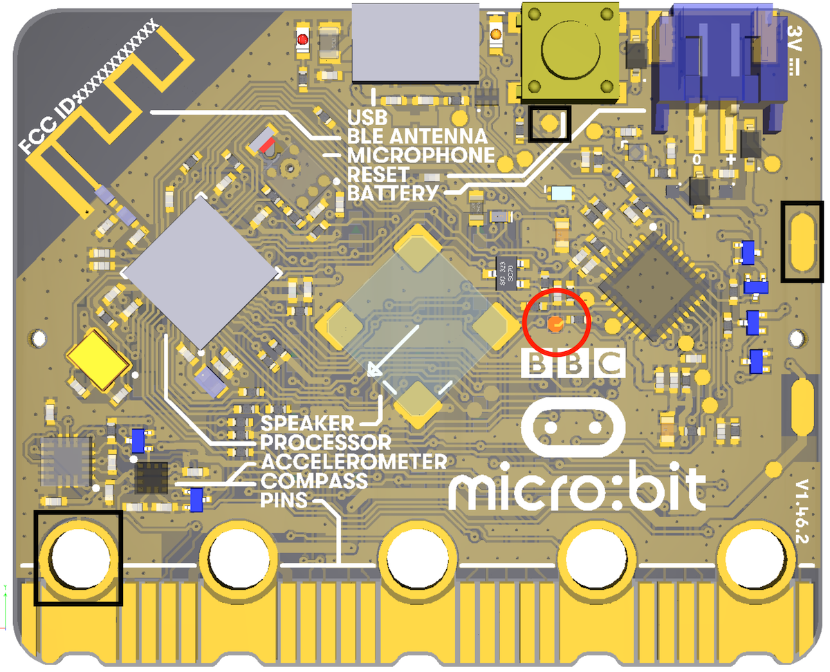
To enter this mode we need to ground TP1 during board power up, this is the BOOTMODE pin in the KL27. To do that, connect with a wire (or something like a paper-clip) from TP1 (the red circle) with any ground point (any black square) as you insert the USB cable into the device.
Bootloader CLI tool
Run the bootloader tool on your OS. These instructions relate to the CLI, but the GUI settings would be broadly similar.
Usage info:
blhost --help
The DAPLink software enables flash protection for the bootloader flash area, so we need to use erase command that also unsecures the flash:
blhost -u 0x15a2,0x0073 flash-erase-all-unsecure
Then unplug the micro:bit from the computer and plug it again, the KL27 should automatically enter the kinetis bootloader. To flash the bin file:
blhost -u 0x15a2,0x0073 write-memory 0x0 kl27_file.bin
To read KL27 flash contents into kl27_flash_dump.bin file:
blhost -u 0x15a2,0x0073 read-memory 0x0 0x40000 kl27_flash_dump.bin